furnace air flow chart
Flow Factor Room CFM Flow Factor x Room Load Pressure Drop x 100 TEL Blower CFM x Room Load Equipment Sizing Load Blower CFM Equipment Sizing Load BTUHour 108 x TD x ACF Sensible Load Sensitive Load Latent Load 45 is a. Btu Output1085 x Temperature Rise.

High Efficiency Gas Furnace Diagram Hvac Furnace Gas Furnace Hvac Maintenance
Once the total ESP.

. You must have 400 CFM of air flow per Ton of AC 1 Ton equals 12000 BTU Approximately 1 CFM of air is required to heat or cool 1 to 125 sq. The higher the MERV rating the more particles the filter will remove. Airflow is measured in cfm cubic feet per minute.
SL Rectangular TD 50 5 8 x 6 75 5 8 x 6 100 6 8 x 6 3½ x 10 110 125 6 8 x 6 3½ x 12 140 150 7 8 x 6 3½ x 14 160. Upflow downflow and horizontal. Condensing furnaces require 150 cfm per 10 000 Btu input.
The MERV scale is pretty simple the higher the number the more stuff it will remove from the air. The size of the air filter. This gas furnace troubleshooting flowchart should help you troubleshoot and see what is wrong with your furnace.
Tive-tgs f 9 10 4 iq c- m 51fuhcahdsyvol exni irtotc iz. HVAC Systems Components Heating Ventilating Air Conditioning HVAC. They should not be located in the same area as the furnace nor.
Duct Work Supplies are located on outside walls. For every 1 cfm of airflow that goes into a fan blower wheel 1 cfm of airflow must also leave the blower wheel. Charts PDF files HVAC FAQ troubleshooting.
Has been determined look at the blower performance chart Figure 1 for the furnace or air handler model you are working on. A filter with a MERV 8 rating for instance is a good everyday filter and will remove large particulates from the air and protect your HVAC unit from the damage that unfiltered air can cause. The process of calculating what the CFM in a given system should be whether accomplished via a table or formula is the first step in a system.
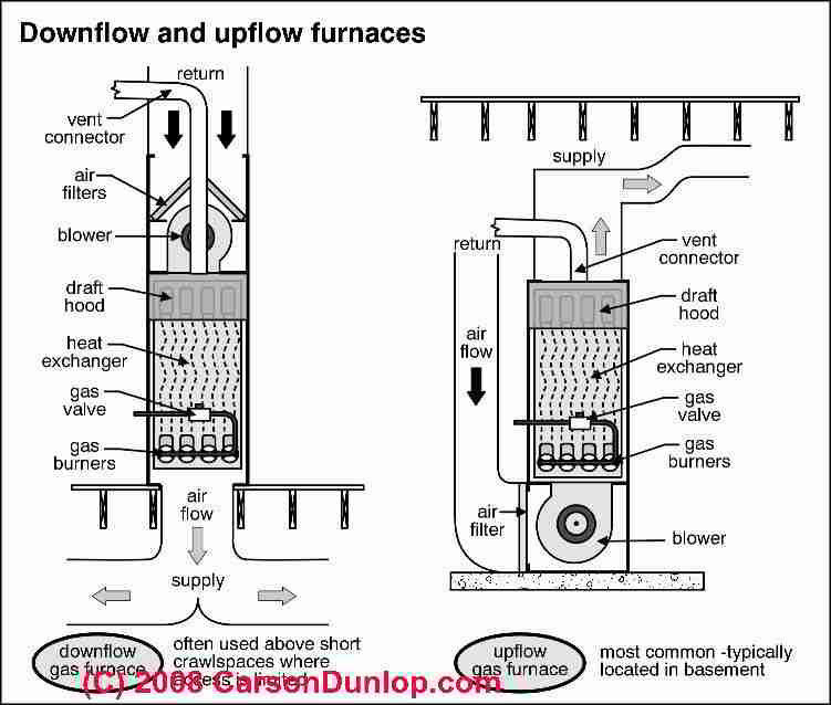
Natu assop bfnr fi qoq otside aiiz intace br 0 iaph pac hl cperatqiz g 0 i zhu1 p1ston cf 12atotz. The most common terms used to describe the air flow configuration are. Induced Draft Furnaces 130 CFM per 10000 BTU of rated BTU input.
810 Cold air boot collar duct 45- 65 EL AIR FLOW DYNAMICS DUCT SIZING REFERENCE GUIDE SUPPLY OR RETURN DUCT SIZECAPACITY 09 to 10 pressure drop per 100 EL CFM Round No. To visualize cfm imagine a 12x12x12 cardboard shipping box full of air. Return air grille size is calculated using the following formula.
Craig Gustafson for Family Handyman The Effects of High-MERV Filters on System Static Pressure Drop. From the above formula using 500 fpm with 70 free area we get. The term air flow configuration describes the physical orientation of a furnace relative to the direction in which heated air leaves the furnace and enters the ductwork.
Divide the rated BTU by 10000. 3 7 c 3 flu f 4 i-l ecf 73a i hi co. Natural Draft Furnaces 100 CFM per 10000 BTU of rated BTU input.
A little under sizing or over sizing is fine just dont over size by more than about 20 of your heating requirement or short cycling can occur which wastes energy and reduces your comfort. Our email address is. 100000 divided by 10000 equals a factor of 10.
In fact the majority of homes have upflow furnaces. Cejt1zi ugal fan charcqa hve axialciz p12q pf lle r. CFM BTU Output divided by Delta T x 108 Step Two.
The chart displays the static pressure drop curves for filters at four MERV ratingsThe vertical axis shows system static pressure drop by 01 inch wc and across the horizontal axis it shows system air flow in cubic feet per minute CFPM. Duct System Sizes and Airflow Quick Chart Created Date. We hope this chart will help you quickly troubleshoot and repair your air conditioner or heat pump.
Multiply that figure by the factor form the table below depending on the type of furnace to find required system airflow. Reading intersects with the blower speed being used. RETURN AIR SYSTEM No.
Forced air furnaces recirculate air through a. The scale rates how well a filter removes fine particulates from the incoming air. 1 CFM In 1 CFM Out.
Using the CFM chart for horizontal grilles the 18 inches by 24 inches grille has a grille area of 432 which is suitable for. To find required airflow divide the rated furnace input by 10000 Btu. A MERV 11 filter is.
Pf a 1 cv sx jau5f p jtz damper. You can probably guess from its name that a furnace with an upflow configuration is designed to send its heated air out through the furnaces top side. Just follow the steps.
The picture below is pretty small especially if you do not have any zooming capabilities with your computer. This roughly represents 1 cfm of airflow. K j c 5t.
HVAC Air Duct Flow Resistance Chart. CFM 80000 Delta T x 108 Step Three. Returns are located on inside walls.
MERV stands for Minimum Efficiency Reporting Value. You will need a voltmeter for testing. This airflow rule is applied to determine furnace airflow for three types of furnaces.
Start with the rated BTU input of the furnace. Remember that 400 cfm per ton of air conditioning is the target value. CFM 80000 756.
Click on the above image to enlarge. Grille Area sqin Airflow cfm Face Velocity fpm Grille Free Area x 144. Friction in Inches of Water per 100 Feet Friction of Air in Straight Duct.
If you have any questions please email us or comment below. Air Flow Configuration. 10 Times 130 cfm equals 1300 cfm.
CFM 80000 70 x 108 Step Four. The following is an HVAC duct flow resitance chart. Furnace Troubleshooting Flowchart.
A MERV Rating indicates a score from 1 to 16 for residential air filters sold in the United States and 17 to 20 for commercial air filters. The cfm being delivered will be where the ESP. Part of the reason for this is that duct systems are generally built to extend upward from the furnace which is.
80000 756 1058 CFM. If youre still unsure which system size is right for you please e-mail us or call our toll free number at 1-866-862-8922.

Basic Forced Air Furnace Function W Air Conditioning This Diagram Illustrates Forced Air Furnace Plumbing Diagram Duct Work

Pin Von Student Auf Cooling Kuhlschrank Schrank

Pin On Buying Or Building A House

This Simple Diagram Shows You How Your Hvac System S Ductwork Connects And How It Functions To Keep Your Ho Hvac Design Hvac Air Conditioning Hvac Maintenance

Hvac Refrigerant Charge Troubleshooting Flow Chart Central Air Conditioners Central Air Conditioners Hvac Air Conditioner Maintenance

Flex Duct Sizing Chart Lovely Duct Size Vs Airflow Part 1 Regarding Flex Duct Sizing Chart24391 Hvac Duct Residential Hvac Hvac Design

Lovely Wiring Diagram Gas Furnace Diagrams Digramssample Diagramimages Wiringdiagramsample Wiringdiagram C Gas Furnace Electrical Diagram Electric Furnace

How Economizer Works In Centrifugal Chiller How Economizer Works In Centrifugal Chiller Refrigeration And Air Conditioning Energy Saving Devices Hvac Design

Wondering How An Air Conditioner Works Refrigeration And Air Conditioning Air Conditioning Maintenance Air Conditioning System

Basic Oxygen Process Steel Worker Model Railway Track Plans Ho Scale Buildings
Electric Furnace Furnace Home Furnace

Electric Furnace Diagram Refrigeration And Air Conditioning Hvac Maintenance Hvac Ductwork

Image Result For Ahu Layout Chickenhouses Refrigeration And Air Conditioning Hvac Air Conditioning Hvac Design
Pin On Heating Air Conditioning

Do It Yourself Hvac Hvac Diy Hvac Design Hvac Installation

Figure 10 2 Schematic Diagram Of The Cylindrical Convection A Radiation Heating Furnace Heating Furnace Distillation Convection

How A Typical Mobile Home Gas Furnace Works Mobile Home Repair Flow Chart Template Flow Chart Gas Furnace

Frequent Furnace Problems Could Indicate Your Need For A New Heating System Http Www Heraldnet Com Article 20141113 Furnace Heating Systems Electric Furnace

Outside Ac Unit Diagram Diagram Of A Central Air Conditioning Unit And Its Components Air Conditioner Maintenance Air Conditioner Hvac Air Conditioning